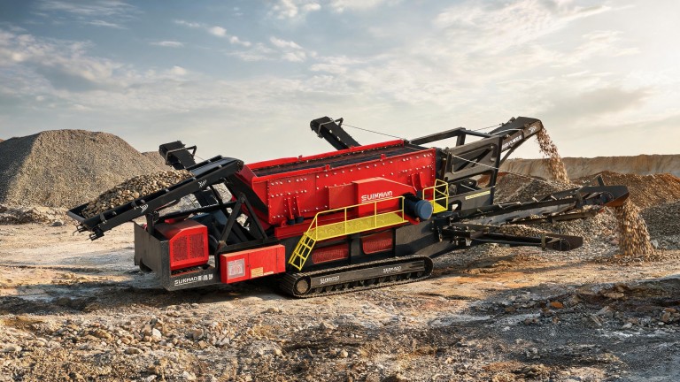
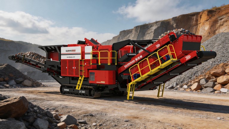
This article focuses on a mineral processing plant designed to handle three size fractions: 0–5, 5–20 and 20–40 mm. It describes the plant’s block diagram, the functional purpose of each section and the specific aspects of processing each size class of material to achieve maximum efficiency in the separation and preparation of the raw materials.
General principle for designing the complex’s circuit diagram
The plant layout is designed around the principle of the raw material passing sequentially through the separation units, with each stage tailored to a specific size range of fractions, which prevents individual units from becoming overloaded and ensures precise separation without unwanted mixing of particle size classes. Each element of the system operates as a single, integrated unit, adapting to the characteristics of the incoming material.
Characteristics of processing the 20–40 mm fraction
The 20–40 mm fraction, being the coarsest, is first fed onto a vibrating screen with large mesh openings, where it is separated from the finer particles immediately after the raw material is fed in. This unit handles the heaviest load in terms of mass, so its structure is reinforced to withstand impacts from solid chunks; after separation, the fraction is sent to the finished-grade storage area or for further crushing if necessary.
Processing of the 5–20 mm fraction
After the coarse fraction has been separated, the remaining flow is fed to a second screen with mesh sizes of the appropriate size, where the 5–20 mm fraction is separated. This size class is the most versatile for most industrial applications; therefore, the process layout provides a separate channel for its collection, with the option of quickly redirecting it to other production areas without halting the entire plant.
Working with the 0–5 mm fraction
The material remaining after the two separation stages, which falls within the 0–5 mm fraction, passes through a final fine screen and is then directed to a separate hopper. This fraction requires particular attention to prevent dust formation; therefore, the relevant section of the process is equipped with local extraction systems that gently capture fine particles without disrupting the natural flow of material.
Advantages of the proposed scheme
This system is characterised by high reliability, minimal loss of raw materials during separation and ease of maintenance. Each unit performs only its own strictly defined function, which reduces the risk of the plant failing, whilst the flexible configuration allows the process to be adapted to the changing characteristics of the feedstock without major design modifications.